About Relays - Title Image

About Relays

Sequence Control Course Logo

Sequence Control Course

Sequence Control Course Recommended Learning Materials

An explanation of relays — the foundation of sequence control. Since ladder diagrams are based on relay circuits, understanding relays leads directly to easier learning of ladder diagrams. This page explains NO contacts (a-contacts), NC contacts (b-contacts), and timer relays clearly using illustrations and videos.

Created: 2010
Updated: April 21, 2026

What Is a Relay?

This section explains relay circuits — the fundamental basis of sequence control. Understanding relay circuits makes it significantly easier to create PLC programs (ladder diagrams). Let's first look at what a relay is.

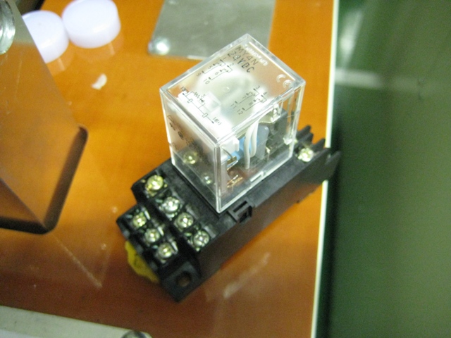
Relay external appearance photo

The photo above shows a typical relay. It is attached to a terminal block so wiring can be done with screws. Normally, the transparent relay body and the black terminal block are purchased separately. What role does this relay play?

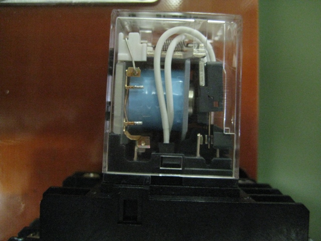
Relay coil (side view photo)

The photo above is a side view of a relay. The blue-taped part inside is the coil. When voltage is applied to this coil, it becomes an electromagnet and attracts the contacts on the right side. The attracted contacts create a switching action. Coils come in AC and DC types, so always check the voltage and type before use.

Basic relay operation: Apply voltage to the coil → becomes an electromagnet → attracts the contacts → contacts switch ON/OFF like a switch

Relay internal structure illustration

Relay Contacts: NO Contact (a-contact) and NC Contact (b-contact)

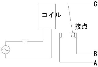
Because the photos are hard to follow, let's use illustrations. The illustration below shows a relay in its normal (de-energized) state.

Relay normal state illustration

In this state, contacts C and B are connected (conducting), and C and A are separated. Next, when voltage is applied to the relay coil, the coil becomes an electromagnet and attracts the contacts.

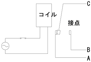
Relay energized state illustration

After the coil is energized, C and A become connected (conducting), and C and B separate.

  • NO Contact / a-contact (C–A): Normally open — no continuity normally, turns ON when the coil is energized
  • NC Contact / b-contact (C–B): Normally closed — continuity normally, turns OFF when the coil is energized
  • COM (Common): The common terminal (C) shared by both the NO and NC contacts

Relay Socket

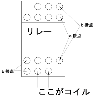
Relays are housed in a transparent cover, and those with 2 or 4 contacts are commonly used for control purposes. The relay terminals protrude downward and are typically inserted into a terminal block (socket) for use. Let's confirm the terminal arrangement when inserted into a socket.

Relay socket terminal arrangement diagram

The figure above shows a typical arrangement. Terminal numbers are marked on both the top of the relay and on the socket side. Generally, the inner terminals form the NO (a-contact). Always verify this when using a relay for the first time.

Operating a Relay

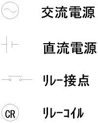
Let's now connect and operate the relay. First, define the electrical symbols as shown in the diagram below.

Electrical symbols reference diagram

These are simplified symbols. Symbols may vary by manufacturer, but they are adequate for understanding circuits. Let's look at a simple circuit.

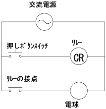
Push-button switch and relay connection circuit diagram

In the diagram above, pressing the push-button switch sends current to the relay coil, the contacts operate, and the lamp lights up. Releasing the switch turns the lamp off. This circuit itself is no different from directly switching a lamp with a push button, but the next circuit shows why a relay is useful.

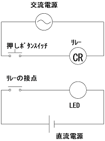
Relay circuit for different voltage control

In this circuit, the lamp has been replaced with an LED. Since an LED operates on DC power, it cannot be directly connected to an AC push-button switch. The relay contact is used to switch the DC LED circuit. By using a relay, circuits operating at different voltages or from different power sources can be safely switched.

About Timer Relays

A timer relay has the same basic structure as a regular relay, but differs in that the timing of contact operation can be set to any desired delay.

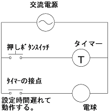
Timer relay circuit diagram

In the circuit above, if the timer is set to 1 second: pressing the push-button switch sends current to the timer coil. However, the contacts do not operate immediately — instead, the lamp lights up 1 second later. In this way, the timing of operation can be shifted using a timer. Timer relays are an extremely important component in sequence and relay control.

Now that you have a solid understanding of relay basics, the next section explains how to input signals from sensors into relays. A control circuit is meaningless if it cannot receive input signals, so let's confirm the signal input method before moving on to relay control.


→Next Page: Signal Input

Frequently Asked Questions (FAQ)

What is the difference between a NO contact (a-contact) and an NC contact (b-contact)?
A NO contact (a-contact) is normally open — there is no continuity until the coil is energized, at which point it conducts. An NC contact (b-contact) is the opposite — it normally conducts, and loses continuity when the coil is energized.
What is the COM (Common) terminal?
It is the terminal shared by both the NO and NC contacts. It is labeled "C" or "COM" and called "common." In relay contact circuits, this common terminal serves as the reference point.
What is a timer relay?
It has the same basic structure as a regular relay, but allows you to set a delay time between applying voltage to the coil and the contacts operating. A dial on the top is used to set the time, and operation is delayed by that amount.
Why are relays used in control circuits?
Relays allow circuits operating at different voltages or from different power sources to be safely controlled through their contacts. For example, they are used to operate DC-powered sensors or LEDs from an AC-powered control circuit.
Sequence Control Course Recommended Learning Materials Banner

The "Illustrated Introduction: Understanding the Latest Sequence Control and Circuit Diagrams" is available as a Kindle (eBook) edition. If you prefer the paperback version, please select "Paperback" in the format options, or purchase from the top page.

Sequence Control Course Banner
Copyright (C) 2010 Sequence Control Course, All rights reserved.