Ladder diagram
Sequence Control Lesson
![]() Sequence Control Lesson
Sequence Control Lesson
![]() Basic lecture
Basic lecture
![]() Ladder diagram
Ladder diagram
Ladder diagram is the language used for programmable controllers. Write it like a relay circuit.Ladder diagram is essential for learning sequence control, and more general programmable controllers adopts ladder diagram. When controlling equipments etc. with programmable controllers, it is necessary to understand the ladder diagram, and if you do not know the ladder diagram, control with programmable controllers is almost impossible.
A ladder diagram is a drawing expresses a program in the format of relay symbols.That's why I am making a relay circuit in a personal computer. Although I am planning to explain it easily from a beginner on this site, please understand at minimum that what kind of relay control is, even a little.
If you are new to relay control, please study from Relay control. If you are a novice beginner, please study from Relays.
Let us explain the ladder diagram. We use the relay circuit described at the end of relay control to use.
First remove the input part of the sensor from the relay circuit. When inputting a signal to the programmable controllers, there is no need for a circuit to operate the relay with the sensor, as done with relay control. For example, if you connect the sensor directly to the terminal block "X0", you can just write the contact point "X0" on the program. The connection method will be explained later.

I removed the sensor part from the relay circuit described at the end of the "relay control".If you can design the relay circuit easily, I think that the ladder diagram can be understood quickly.
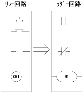
Please change the contact and coil shape as above. At this time, both the contact of the push button switch and the contact of the relay will be the same symbol. Please also remove the power supply circuit above. Left and right vertical bars will be left. Then it will be like this.
I think I've seen it if you have studied ladder diagrams even once. The ladder diagram is basically for easy creation and editing of the relay circuit in the screen of a personal computer or the like.
First "CR" has changed to "M". This "M" is called an internal relay.(Internal I/O Area) Internal relays are virtual relays. There are many virtual relays in the programmable controllers. Relay can be used with M. We will use this relay to create self-hold. Since the internal relay "M" has a number, it can be used a lot.And in the case of the relay circuit, only about 4 contacts of the relay could be used, but any number of internal relays can be used. However, one coil can be written as a coil.
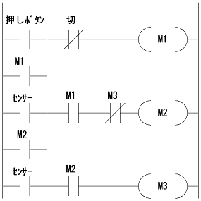
But as it is, it will not move yet. It is only in the program that moves.It will not operate unless it is output from programmable controllers. Add a coil to output. "Y0" - "Y2" part was added.
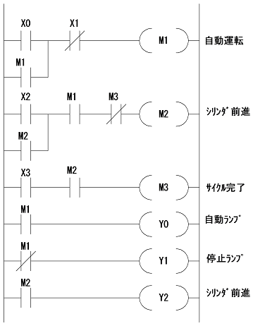
I will explain in order.Use the contact "X" for input from the sensor and push button switch.It is to connect the sensor to the terminal "X" of the programmable controllers.The connection method will be described in detail later, but the pushbutton switch is connected to the terminal "X0". The OFF button is connected to "X1". The photoelectric sensor is connected to "X2" and the cylinder sensor is connected to "X3".When you push the push button switch, "X0" turns on. "X2" turns on when the photoelectric sensor responds.
Next is the output.Although the program operates in the programmable controllers, the cylinder does not operate unless it is output from the programmable controllers.Use [Y] to output.
An automatic lamp is connected to the output terminal "Y0" of the PLC.In the ladder diagram, you can output it by writing "Y0".
Since the output terminal of the programmable controllers is like a contact of a relay, it operates like a switch using contacts.
In this way, the input is "X", the output is "Y", the symbols are predetermined. The internal relay explained earlier is also decided as "M".
Enter "X0" of the push button, "M1" will work."M1" will self-hold. Please look at the output part. If "M1" works, "Y0" will work. The automatic lamp lights up accordingly. "Y1" of stop lamp is b-contact of "M1".That is, it lights up when "M1" is not inserted and turns off when "M1" is entered. "Y0" and "Y1" behave exactly the opposite way.
The state that "M1" is entered is the automatic operation state.Operating the photoelectric sensor in this state will cause "M2" to work. This is a cylinder advance command. As long as this output comes out, the cylinder advances. When the output turns off, the cylinder moves backward.(Solenoid valve with such characteristics is called single solenoid) "M2" will work and turn on "Y2" and the cylinder will move forward. Next, reed switch "X3" turns on. "M3" turns on when reed switch "X3" is turned on while cylinder advance command "M2" is issued.
When "M3" turns on, "M2" disappears because the "M3" b-contact is in the self-holding condition of "M2". When "M2" disappears, "M3" disappears. When "M2" disappears, "Y2" for cylinder advance also disappears, so the cylinder moves backward. This is the cycle completion.
I explained briefly, this is the basic of the ladder circuit. As soon as you get used to it you will be able to understand. And basically it is basic, but since the ladder diagram is only coil and number, if you do not write a comment, you will not understand the meaning.
The minimum knowledge to learn sequence control is here. I will step into the world of sequence control from now on, but I think that it often happens and fails as expected. In such a case, it is important not to give up, try many times trying and studying many times. This difficulty is a shortcut to progress.
Now we are going to explain sequence control.Programmable controllers will be called PLC.
This is a Japanese reference books.