Relay control
Sequence Control Lesson
![]() Sequence Control Lesson
Sequence Control Lesson
![]() Basic lecture
Basic lecture
![]() Relay control
Relay control
Using a relay, create a control circuit.It is basis of the ladder diagram.
First, connect the switch and the coil.
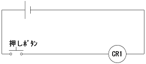
Press the pushbutton switch to activate the relay.If you release it, the relay returns to its original state.This alone is meaningless circuit. Press the push button switch to activate the relay and leave the relay running even if you release it.
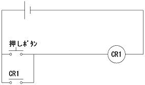
The a-contact of the relay and the contact of the push button switch are connected in parallel.Press the pushbutton switch to activate the relay.Then the contacts of the relay will also activate. As a result, the contact of the relay operates the relay instead of the push button switch.The relay will continue to operate even if the push button switch is released.This state is called "self-holding".
"Self-holding" can not be release because it keeps its own self holding. It is necessary to add contacts to release.
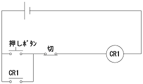
Add the b-contact of the switch as shown above.Self-holding is canceled if stopping current supply to the coil of the relay.Even if the main power supply is cut off, the self-holding is canceled. In the circuit diagram above, pressing the pushbutton switch will activate the relay, and pressing the "off" switch will release the self-hold. Since the relay has a plurality of contacts, if another contact which is not used for self-holding is used, a green lamp is connected to the a contact and a red lamp is connected to the b contact so as to supply power to the lamp If you push the push button, green lights up, if you press the off button the green will go out and the red lamp will light up.
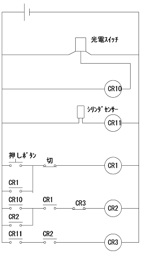
This circuit is operated by DC. AC is also possible, but because there are sensors etc, I will do it in DC."CR10" and "CR11" are for sensor signals. The relay will tick when you react the sensor.
Pressing the push button turns into automatic operation. Press the OFF button to stop.If you react the photoelectric switch during automatic operation, operate the cylinder.When cylinder operation is completed, return the cylinder to its original position. A cylinder is one that moves forward or backward when air is introduced.Use a relay to operate the cylinder.
When push button switch is pressed, CR1 operates. Since this is self-holding, CR1 will continue to operate if you press it once. If you press the off button, CR1 will stop. That is, CR1 is automatic operation. If a lamp is required, it lights at the a-contact of CR1.
If CR10 and CR1 operate, CR2 will operate.That is, when the photoelectric sensor reacts in the automatic operation state, CR2 enters.Move the cylinder with CR2 relay. The relay of CR2 is also self-holding. When sequence control is performed with a relay, basically self-holding is repeated.
The cylinder operates when CR2 operates. When the cylinder goes to the forward end, the cylinder's reed switch reacts. This reed switch is CR11. CR 11 operates when CR 2 operates. That is, when the reed switch reacts when the cylinder operates, CR3 operates.
The self-holding condition of CR2 has CR3 inoperative. When CR 3 operates, CR 2 self-hold is canceled. When CR2 stops, the cylinder returns. Furthermore, CR3 also stops. The entire circuit is reset. Repeat the same operation if you react the photoelectric sensor again. This is the basis of relay control.
CR 3 will not operate even if CR 11 operates alone.In this way it is important to put the conditions accurately. Otherwise the circuit will operate from the way and it will be in extremely dangerous condition. As in the circuit diagram above, the control to operate the coils in order is called "stepping control" in Japan.
Precautions for relay control.It is the response speed of the contact.It takes about 20 ms (0.02 sec) until power is supplied to the coil and the contacts are connected.More importantly, it is quicker for the b-contact to break than for the a-contact. When designing a circuit by considering it to operate at the same time, the relay may chatter.This is a symptom that occurs because the power supply to the coil is cut off before the a contact comes into operation by the relay.
This is a Japanese reference books.