Start up software
Sequence Control Lesson
![]() Sequence Control Lesson
Sequence Control Lesson
![]() beginners'
beginners'
![]() Start up software
Start up software
It is an easy way to use software.It will use software GX Developer or GX Works2.Since I am Japanese, I use Japanese software.
I do not use English software, so there may be errors in the notation.
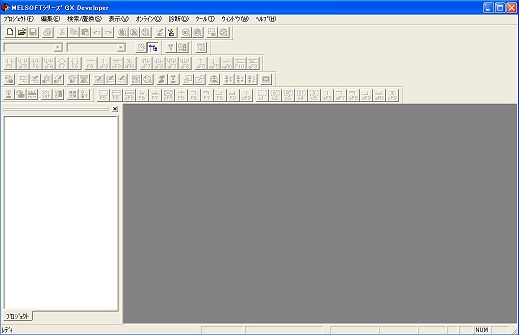
When you start GX Developer, the above screen will be displayed. In the upper left menu, click "Project" → "Create New Project".
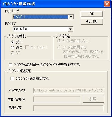
Set the type of PLC on this screen. Since I'm thinking of using FX1N's PLC this time, I changed the PC series to "FXCPU" and changed the PC type to "FX1N (C)". Please set according to the sequencer you want to use. After setting, please press OK.
Next, select "Tools" → "Options" in the menu above.
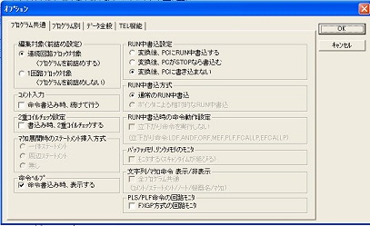
There is an item of comment input on this screen. Please make a check in "Continue at instruction writing". After checking please press OK. If you do this, after entering the command, the comment input window comes up. Even if you do not enter a comment, it does not affect the program, but please be sure to input it because it will be unknown.
In the case of "GX Works" it is a little easier, the following screen appears when inputting a circuit, there is a setting button on that screen.
When you input the circuit, you can press the button on the red frame once to complete the setting. There is no need to press each time.
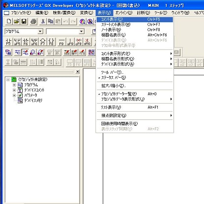
Next, check "Show" → "Comment display" in the above menu. By this work, the comment written by yourself on the circuit will be displayed.
In the case of GX Developer, data is saved as multiple files as a project, not as a single file.Both settings are possible for GX Works2.
Next, I will explain the mode. GX Developer and GX Works2 have read mode, write mode, and monitor mode. Read mode is the mode used to check the circuit. Write mode is used when editing or adding a circuit. The monitor mode is actually connected to the sequencer and you can check how the circuit is currently operating.
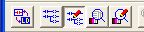
There is an icon like the above in the upper left of GX Developer. Clicking on this will change the mode. Ignore the icon on the leftmost one away. Read mode, write mode, monitor mode, monitor write mode are from the left. Writing can be performed while monitoring the monitor writing mode. Whether it is easy to use depends on who uses it, so please judge yourself when you get used to it. By the way, I do not use it.
When you get used to switching modes, use the shortcut keys.
Key of "F2": Write mode
Key of "F3": Monitor mode
"Shift + F2": Read mode.
GX Works2 Basically the same.
* For the icon that is the leftmost one icon, switch the circuit display to list mode. This mode is not used as it is almost never used now.
Although it is a difference in operation, in the case of reading mode, inputting something will result in a search. In other words, entering "X3" will search X3 one by one. In the case of writing mode, input "X2" will be input instead of search. If you simply look at the circuit, you can operate the read mode more easily. In writing mode, you can search by pressing "Ctrl + F".
The monitor mode is the same as the read mode, and you can operate it while confirming whether the contact of the sequencer is present at the moment. However, because there is a communication speed, it takes a little time to scroll the screen etc. Please switch the mode well in accordance with your work. If you get used to it you will be able to do it naturally.
Next is the contact input. The following icons are lined up.
It is a symbol of a ladder diagram. You can also type in it by clicking on it, and a sign like "F5" etc is written. For example, if you press "F5", it becomes input of a-contact. In actual work, I will not do anything like clicking the button with the mouse. As you get used to it you will be able to use keys such as "F5" naturally. "SF5" holds "Shift" key and presses "F5" key.
Finally, I will explain the explanation on the left side of the screen.
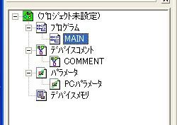
This is the content of the project you are working on now. Double click "Program", "MAIN" appears. This is about the ladder diagram you are creating now. Double-click "Device Comment", "COMMENT" will appear. Double-click "COMMENT" to enter the comment editing screen. From here you can set comments for each device number. Double-click "MAIN" to return to the ladder diagram. Last parameter. This is the setting of the PLC. Although I do not have much opportunity to touch it the first time, I can make various settings.
Next we will create a ladder diagram.
This is a Japanese reference books.