Wiring connection method of PLC
Sequence Control Lesson
![]() Sequence Control Lesson
Sequence Control Lesson
![]() beginners'
beginners'
![]() Wiring connection method of PLC
Wiring connection method of PLC
I will explain wiring method to PLC. It is input of power supply, signal input from sensor etc., output to lamp and power.
PLC has various kinds. Basically Mitsubishi Electric's PLC will be used.Since it is a beginner class this time, I will use the FX series.
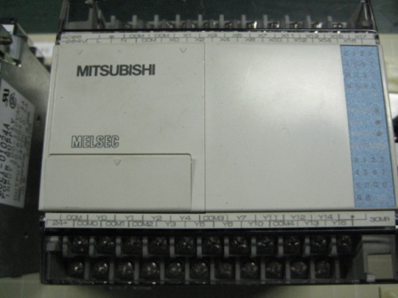
Briefly explaining the FX series, it is a low price version of PLC. However, recent sequencers have sufficient performance even in cheap versions. However, recent PLC has sufficient performance even in low price version.The picture below is "FX1N" PLC. It has a standard terminal block and it also has the minimum required input / output as standard, so there is no problem if it is a simple device. On the contrary, it is necessary to select the upper model (eg Q series etc.) for the input / output unit etc and make the PLC of the function you want to use.
On the left side is written "MELSEC". Below that there is a cover like a lid. Here is a port for connecting with a PC. This type is RS-422 communication method. Well, it is confusing even if I talk about the communication method suddenly, so connect this round connector and a personal computer and write the program from the personal computer.
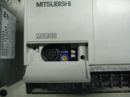
There is a switch on the side that opened the lid. It is "RUN" on the top, "STOP" when you knock it down. The program is executed in the RUN state. It does not work in the STOP state. In other words, you need to set it to "RUN" to execute the written program.
Power supply input
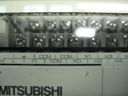
Input of power supply input to "L" and "N" terminals. Although 100 VAC is entered, it may be different depending on specifications, please check.
Wiring should be simple as shown in the figure below. The PLC can also output 24VDC, but if the capacity is small and driving a large load, the PLC will not start up. There is no problem as long as it is used as a sensor power supply, but when operating a load more than that, let's install a DC power supply.
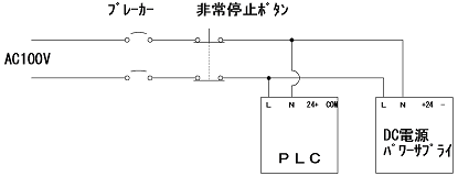
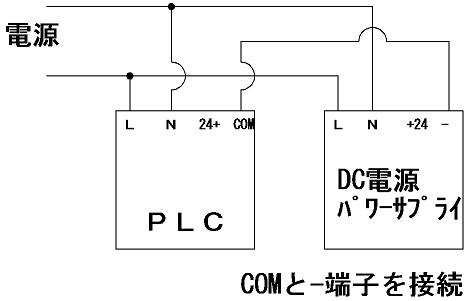
As shown in the figure above, when using the DC power supply as the sensor power supply, connect the minus terminal of the DC power supply and the COM of the PLC.
Make the ground side the same.If not connected in this way, input signals can not be input to the PLC when the sensor is driven from the DC power supply.
(In case of sink output)
Conversely, do not connect the 24 + terminal of the PLC and the positive terminal of the DC power supply. The voltage is not exactly the same 24V even at both 24V.
又、電圧の違うDC電源でもグランド側を接続することは問題ありません。
Signal input
Let's input signals to the PLC. Signal input is easy. Connect as shown.
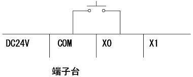
"X" is the address (symbol) of the input of the PLC. "X0" ~ Terminal blocks with numbers are lining up. We connect the signal wires here. In other words, only the number of terminal blocks can be input. When actually manufacturing equipment, you have to check the number of I / O well. In "relay control", the relay was operated by the sensor, and the relay circuit was operated using the contact of the relay. In the PLC, this sensor activates this "X" contact. It is input by short-circuiting the terminal block of COM and the arbitrary "X" terminal block. If "X 0" and COM are short-circuited, the lamp of "X 0" on the surface of the PLC will light up and the signal will be input. This "X" input is used in the program of the PLC. If you connect a pushbutton switch or the like as shown, press the button to input the signal. Signals are input if the wiring is done in the same manner for the 2 wire type of the reed switch.
How do you input the types that require power supply like thrubeam or reflective sensors? Enter it as shown below.
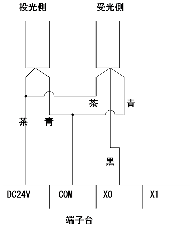
It looks complicated, but it's easy. First connect the brown wire to +24VDC. Completing it by connecting the blue wire to the COM terminal and the black wire to the "X" input terminal. There is only an increase in 24 V wiring. Please pay attention to polarity. There are only two brown and blue lines on the transmitter side of the thrubeam sensor.This is just a power line, just connect brown to 24VDC and blue to COM (minus side). The 2 wire type of reed switch (cylinder) is brown and blue wire.Connect the brown to the "X" input terminal of the reed switch. Connect blue to COM.
Output
Even if you connect only the input, only the programs in the PLC will work unless the output is connected, but you can not operate the equipment.
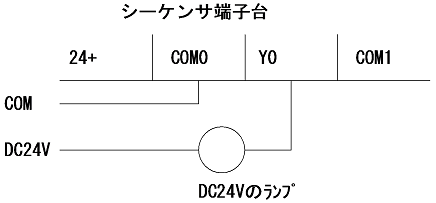
"Y" is the address (sign) of the output. Please note that "COM 0" here is different from COM described in input. It is supposed to light the lamp. Connect the plus from the power supply to the positive side of the lamp. Connect a minus power supply to COM0. Next connect "Y0" to the minus side of the lamp. When "Y0" is output from the PLC in this state, the lamp lights up.
Structure of output.
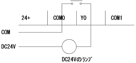
The output terminal of the PLC simply has contacts. There are many kinds of PLC, but the type described here is the relay output type. That is, when "Y0" is output, the relay contact of "Y0" will operate. Use the contacts to output. Therefore, in the program the output is called a "coil".
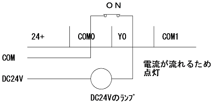
In this way the lamp on because the contact closes and the current flows. This time we did with DC load, but since it is just contact, it can operate even with AC load.
However, since there is a contact capacity, if you attach a very large load directly, the contact breaks.
There is also a transistor type as a contact. Since there is polarity in this case, it will not work unless it is polarized like the illustration above. Therefore we recommend connecting with this polarity from the beginning.
(In case of sink output)
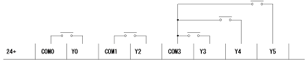
When PLC is FX type, the output is divided like the illustration above. In other words, it is also possible to wire AC and DC together. I will introduce samples.
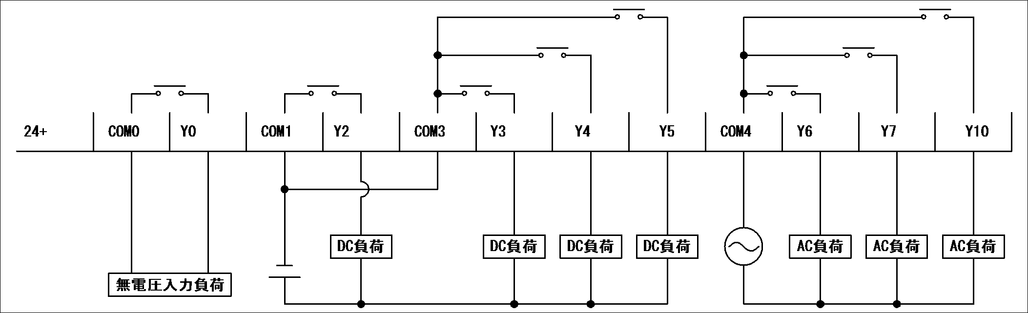
Connected to "Y0" is a no-voltage load, it is a type that shorts the two wires coming out of the load. Since it is impossible to apply voltage, it is divided as shown in the figure. "Y2" - "Y5" load DCs. In this case "Y2" and "Y3" - "Y5" are independent. Therefore, "COM1" and "COM3" are connected. "Y6" - "Y10" are the load of AC. This is a connection example so you do not have to connect this way.
This completes the explanation of simple wiring. This time we explained with PLC with terminal block, but most of the top models are not equipped with terminal block as standard. It will be in the form of adding an input / output unit. Also, there is no terminal block on the unit and it is a connector. And the output COM is not independent like the illustration above. "Y0" to "YF" are not independent. In the FX series, both input and output are started from 0 and the digit rises at 7. That is, next to "X7" will be "X10" 8 points each. Q series and so on are 15 points of "X 0" ~ "X F". As address changes according to unit number, please be careful.
Recent PLCs are becoming more compact. Since the output is almost transistor output, please check well when purchasing.
Now that you know how to wire to the PLC, I will start up the software to write the circuit to the PLC.
This is a Japanese reference books.