A simple ladder diagram
Sequence Control Lesson
![]() Sequence Control Lesson
Sequence Control Lesson
![]() beginners'
beginners'
![]() A simple ladder diagram
A simple ladder diagram
Create a simple ladder diagram.
First, decide the behavior appropriately.
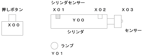
Assuming that there is a cylinder, a sensor is attached to it.The cylinder has a reed switch for detecting the forward end and the backward end.
And there is a push button switch.Activate this cylinder and check if there is an object first.
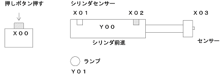
In operation, the cylinder moves forward when the push button switch is pushed. Confirmation that the cylinder has completed the forward movement is done with the reed switch."X2" turns on when the cylinder completes forward movement.
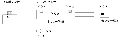
If the sensor at the cylinder tip does not respond after the cylinder moves forward, the cylinder moves backward as it is. If there is an object in front of the cylinder, the sensor at the cylinder tip will react.
When the cylinder moves forward and a certain time elapses, the cylinder is retracted by confirming the end.
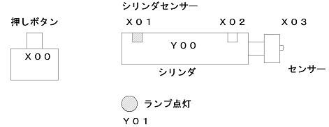
If there is an object in front of the cylinder, light the lamp for 1 second after the cylinder retracting motion. If there is nothing in front of the cylinder, the lamp will not light up.
With the operation so far as one cycle, if you push the button again, this operation will be repeated. However, if you hold down the button, the second action will not be performed.
The point here is to make the cylinder move backward to complete cycle operation after the cylinder moves forward, whether or not there is a thing. Therefore, the sensor at the cylinder tip can not be used as the condition of the cylinder backward motion.
Let's make circuits. Please connect wiring first. Wiring connection is the work of connecting sensors etc. to PLC. I will not explain it here, but it explains Wiring connection method of PLC. However, connect I / O as shown in the illustration above.
Launch the software and create a new project. The CPU should be connected to the CPU. Here I will select the FX series.
First part is the first part. Pressing the button will move the cylinder forward and move backward.
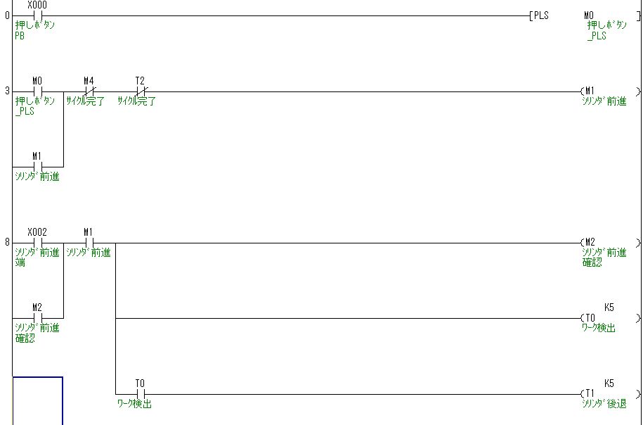
When you push the "X0" push button switch for the first time, it becomes [PLS M0]. This PLS is a pulse, and "M0" turns on for only one scan of "Rising edge" containing "X0".
To put it more simply, when you press "X0", the moment you press it "M0" will turn on momentarily. This is a countermeasure of "Do not let the second action work if you hold down the button" in the operating condition.
Even if you hold down "X0", "M0" will only be on for a moment, so you need to release "X0" once and press again to complete the operation and operate again.
As an input method, press "F8" key and enter "PLS". Then press "space" and enter "M0" and press the enter key to complete.
By the way, setting [PLS M0] to (M0) will work in the same way, but if you keep pressing the push button, it will operate continuously. You need to release the button before the cycle is complete.
The part surrounded by [] is a special command like [PLS M0]. In this case we are going to PLS "M0" command. The part surrounded by () as in (M0) is a coil. Please be careful as it is different.
Since "M0" enters for only a moment, it will self-hold with "M1". Please ignore "M4" and "T2" now. Move the cylinder forward using this "M1" coil. Therefore, when creating a circuit, "M1" turn on, please imagine that the cylinder operates.
When "M1" turns on, the cylinder moves forward, so "X2" of the reed switch turns on. Next we will use this "X2". When "X2" turns on it will self-hold with "M2". Moves forward is completed when "M2" is turned on.
"T0" turns on at the same time "M2" turns ON. This "T0" is a timer, the contacts will behave late. In the illustration above it is "T0 K5". This part becomes the coil of the timer. When the coil of "T0" is turned on, the contact of "T0" operates after 0.5 seconds. "K" is specified in decimal number. If you specify "H", it will be hexadecimal.
To write the timer, press the "F7" key to make the coil write screen. And since it is "T0" this time, enter "T0". Then press "space" once to enter "k5". This will be entered by pressing the Enter key.
To explain the operation, it will confirm "work" with the sensor at the cylinder tip 0.5 seconds after the cylinder moves forward. "Work" refers to the object. "Work" is confirmed at the contact of "T0", and the cylinder is moved backward 0.5 seconds later. In other words, the cylinder moves backward even if "work" is detected or not.
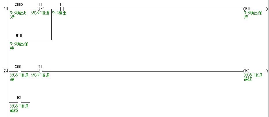
Next is the detection part of "work". When the sensor "X3" at the cylinder tip turns ON, it will self-hold at "M10". This will remember whether "work" has been detected.
"T0" is inserted at a-contact. It is the timing to detect workpiece with the circuit above. Even if the sensor does not operate if it does not exist, it will self-hold if the sensor reacts.
"T1" is inserted at b-contact. This is to prevent the work detection when the "T1" comes in, that is, when the cylinder starts moving backward. Without this, if the sensor reacts during cylinder backward motion, it will self-hold.
If you change the location of contacts, the behavior will change, so please change carefully. For example, if b contact of "T1" is brought to the right side of "T0", the self-hold will disappear at the moment the cylinder moves backward even if the work is detected.
Then, move the cylinder backward with the contact of "T1". At this time, when "X1" turns on it will self-hold with "M3". After retracting the cylinder with "T1", if the cylinder receding end of "X1" turns ON, turn "M3" ON to confirm that the cylinder has retreated.
The following is an explanation of the operation after the cylinder moves backward.
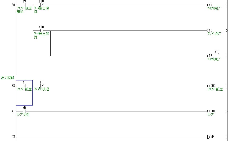
"M3" turns on when the cylinder is retracted. "M10" is ON when work detection is done. First of all, when workpiece detection is not done, "M10" is not on, so the circuit on the b-contact side of "M10" will work. Next "M4" is turned on. This "M4" is designed to stop self-holding of "M1" (cylinder forward motion) at the beginning of the circuit. That is, "M4" turns on "M1" turns off. When "M1" turns off, "M2" "T0" "T1" turns off. Furthermore, "M3" is also turned off, and all the self-holding of the active part is cut off. Then it returns to the initial state. This is the cycle completion. Pressing the push button switch "X0" again in this state repeats the same operation. If you do not pulse the pushbutton switch "X0" here, keep pressing "X0" will do the same operation many times.
"M10" is ON when workpiece detection is done. That is, the circuit on the a-contact side of "M10" operates. Then "M5" turns on. Lights the lamp with this "M5". "T2" turns on after 1 second. This "T2" is the cycle stop signal. When "T2" turns ON, all self-holds disappear. Therefore, the lamp will turn off. This completes the circuit with the lamp on for 1 second.
Finally it is the output part. Without the output part the cylinder will not operate. Because the operation of the cylinder is checked, the circuit also stops halfway.
When "M1" turns on first, the cylinder forward motion. Since "T1" is the cylinder retracting motion, insert "T1" with b-contact after "M1". In other words, the cylinder moves forward with "M1", but "Y0" will not operate by turning on "T1". That is, the cylinder moves backward. Since the cylinder here is operated with a single solenoid, if you turn off the output, it will return to its original position without permission. By the way, when using a double solenoid, it is necessary to output a backward signal with the forward signal turned off. Usually, when using double solenoid, turn off the forward signal with forward movement completed.
Finally it is lamp output. When a workpiece is detected, "M5" is turned on for 1 second, so it just outputs it to "Y1" as it is. There is no particular circuit to turn off, and "M5" will also turn off as the whole circuit is reset after 1 second after "M5" turns ON.
You can create it smoothly if you get used to it, but it takes time to get used to it. Depending on the circuit creation method, it is short-cut to remember the shortcut keys and work. If you switch to a mouse each time you enter a contact, it will not work. Let's get used to it little by little.
The beginner's explanation is over so far. Thank you for reading to the end. The explanation in the elementary level was explained in order, but from the intermediate level we will explain it individually according to the application.
We have summarized the connection method etc with the PLC. Please read it if you can afford.
This is a Japanese reference books.