Creating ladder diagram
Sequence Control Lesson
![]() Sequence Control Lesson
Sequence Control Lesson
![]() beginners'
beginners'
![]() Creating ladder diagram
Creating ladder diagram
I use GX Developer, but GX Works 2 is basically the same.I will make a simple ladder diagram. Please remember the operation method here. Please select the type of sequencer to use from "Project" → "Create New Project".
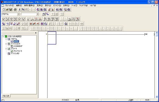
The screen is displayed. I will create a ladder diagram in the large window on the right. Clicking in the window will move the blue square. You can also move using the four - way key on the keyboard.I will write contacts etc inside this square. Let's go back to the upper left for now. Then press the "F5" key.
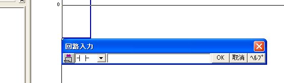
The input screen appears like this. This is to input the a-contact, but the PC is asking for input of contact number.Assume that a push button switch is connected to "X0" of the PLC input terminal. Enter "X0" and press the enter key. If you check "Continue at instruction writing" from "Tools" → "Options", a comment input screen will appear. Let's make comments easy to understand. In this example, it is "pushbutton switch". The switch may be abbreviated as "SW" or "PB" in some cases. After inputting please press the enter key.
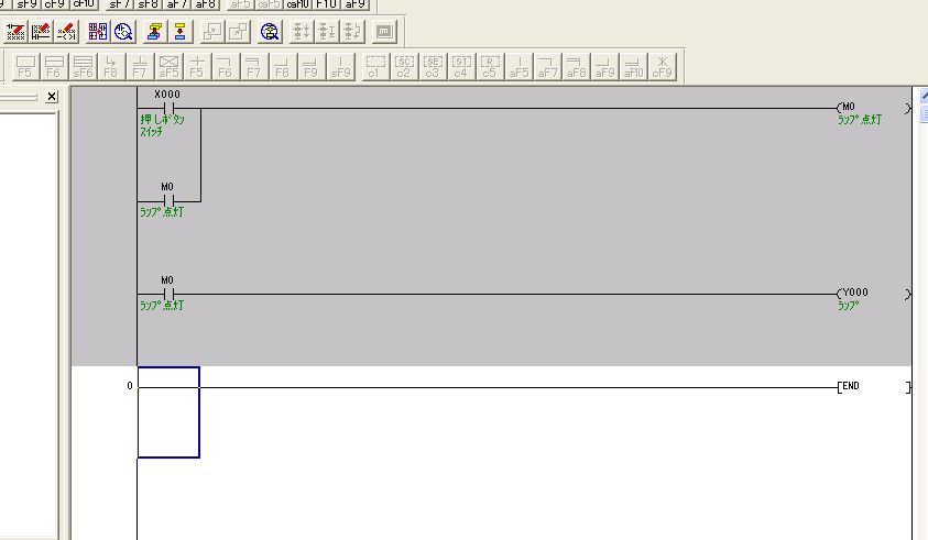
Let's try typing as shown in the figure above. Although the above figure shows comments, if character comment is not displayed, please check "Show" → "Comment display" in the above menu. "M0" and "Y0" on the right side are coils. You can input by pressing the key of "F7". In this circuit, when push button is pushed "X0" turns on, self-holding is applied with "M0" of internal relay. And when "M0" is turned on, it is output to "Y0". If you attach a lamp to "Y0", it lights when you press the button. In this state, the input part is gray. This is still being edited, and this circuit has not been confirmed. Please press "F4" key to confirm.
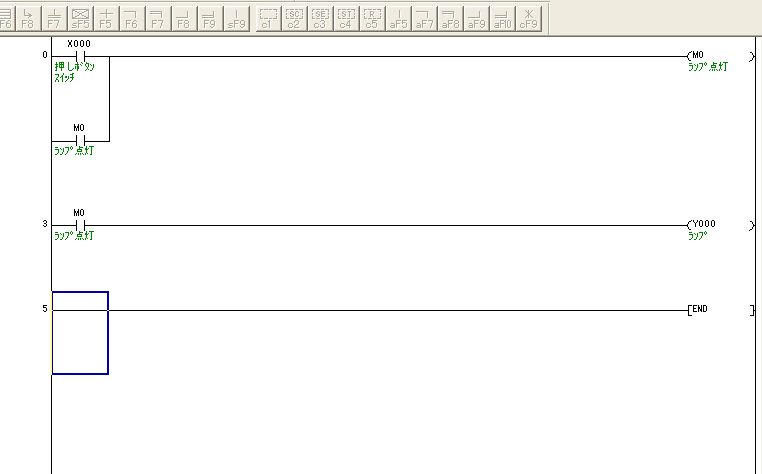
Then the gray of the screen disappears. The circuit is now confirmed. This work is called "conversion". It can also be executed from "Conversion" → "Convert" in the menu. Let's modify this circuit this time. This circuit can not cut self-hold, so let it cut. Add b-contact of "X1".
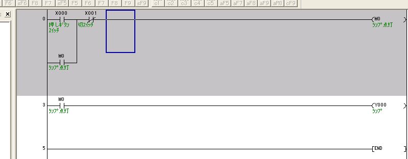
Then, the edited part becomes gray. Since it has not yet been confirmed in this state, convert with "F4". We will proceed with this repetition.
As a supplement, in the above circuit diagram, the contact of "M0" is in parallel with "X0". This can be entered by hovering the cursor under "X0" and pressing "F5" while holding down the "Shift" key.
When the circuit is completed, let's write the circuit to the PLC.
This is a Japanese reference books.