Write to PLC
Sequence Control Lesson
![]() Sequence Control Lesson
Sequence Control Lesson
![]() beginners'
beginners'
![]() Write to PLC
Write to PLC
Configure communication settings before connecting the PLC to the computer. It will be a little complicated, but I will explain in order. The PLC to be connected this time is the FX series.
The FX series has a round connection port, but this is a communication connector for RS422. However, PC generally does not have RS422.
Therefore, the personal computer uses the RS232C port. Connect to the PLC with a dedicated cable from this RS232C port. This cable converts RS232C and RS422.
There are a lot of products with a USB port on the latest PLC, so you do not have to think deeply, but as USB comes out when it comes to a little old series, you need to remember this area firmly.
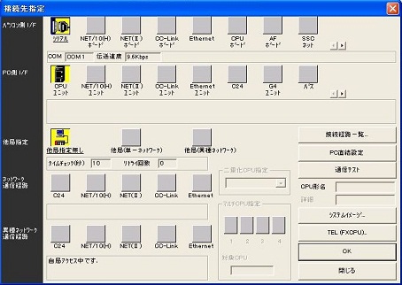
Then, I will make the setting. Connect the sequencer to the computer with a cable and select "Online" → "Specify connection destination" in the menu.
For USB connection, driver installation is required.For details, refer to PLC Connection method.
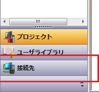
For GX Works, you can set from the project window on the left.
First, set the COM number. The COM port is displayed on the serial part of the interface of the PC. It is COM1 on the screen. This is a setting to connect to the PLC from COM1 of this personal computer. If there are multiple serial ports on the PC side, you need to set which serial (COM) port you want to connect to.Let's double-click on the above icon which is written as serial.
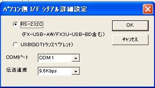
A screen like the one above appears. Select COM number here. Please match the number to be connected. If you connect as USB, select USB. I will not explain the details, but most recent PCs are not equipped with serial ports. The setting when connecting the serial port with USB is RS232C. USB is selected when connecting directly from the PC to the PLC via USB. This is only when the USB port is installed in the PLC. The setting is reflected if you press OK at the end. Although I explained it slightly difficult, in fact there are also cases where you can connect even without setting it in particular. Let's change the number of COM if it is not possible.
If you want to know more, please refer to PLC Connection method.
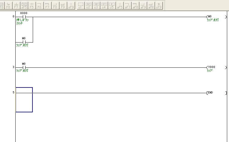
Let's write the ladder diagram that we made to the PLC this time. I will use the circuit above.
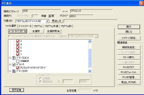
Convert work so that there is no gray area. Then select "Online" → "Write" from the menu. At this time, it is necessary to connect the PC and the PLC and turn on the PLC. If communication settings are available, the following screen will be displayed.
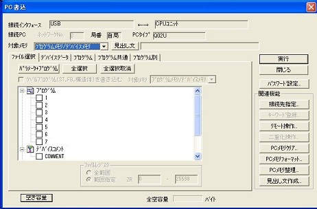
There was no actual FX screen, so this time it will be the connection screen of Q02U. Check the check box on what you write here.
Basically, if you click "Parameter + program" and click OK, there is no problem. Comment etc data can also be written in the PLC, but since the capacity is big, let's write it when the memory of the PLC is left over.
In case of FX, to write comments in PLC, it is necessary to set comment area by parameter setting beforehand.
The writing method described now is a method of batch writing programs etc. Therefore, it is necessary to put the PLC in the STOP state. This means that we have to suspend the equipment temporarily.
(If it is a recent sequencer, you can write it in RUN even if it is only program. Please select only program and write. However, when you select a parameter, you need to put the sequencer in the STOP state.)
Write during RUN
Next we will show you how to rewrite only a part of the program when changing part of the program.
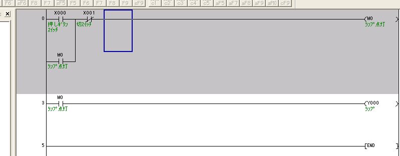
I will change some in this way. Rather than convert normally here, hold down the "Shift" key and press "F4". To execute from the menu, it is "Conversion" → "Conversion (RUN in-progress writing)". Since this can be written while the program is running, it is not necessary to stop the running machine. However, there is a condition, it can not be done unless the program on the PC side and the program in the PLC match. Therefore, in a state that they are in agreement, if you change a part and make a mistake and convert it to normal, it will be inconsistent at that point. To match, please write once from "online" or read.
Write the completed circuit once, then use write during RUN to modify it. During debugging, it is basically written during RUN. Because it is a function you often use, please be sure to remember it.
After writing the program to the PLC, let's read out from the PLC and monitor it in the PLC.
This is a Japanese reference books.